4 - Behavior
First of all a process has an implicit message queue to receive the messages listed in the channels.
A process description is based on an extended finite state machine. A process state determines which behavior the process will have when receiving a specific stimulation. A transition is the code between two states. The process can be hanging on its message queue or a semaphore or running e.g. executing code.
SDL-RT processes run concurrently; depending on the underlying RTOS and sometimes on the target hardware the behavior might be slightly different. But messages and semaphores are there to handle process synchronization so the final behavior should be independent of the RTOS and of the hardware. Since SDL-RT is open to any C code it is up to the designer to make sure this statement stays true !
Note that in a state diagram the previous statement is always connected to the symbol upper frame and the next statement is connected to the lower frame or on the side.
4.1 - Start
The start symbol represent the starting point for the execution of the process:
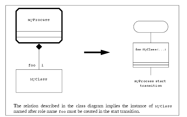
The transition between the Start symbol and the first state of the process is called the start transition. This transition is the first thing the process will do when started. During this initialization phase the process can not receive messages. All other symbols are allowed.
4.2 - State
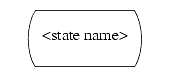
The name of the process state is written in the state symbol:
The state symbol means the process is waiting for some input to go on, the allowed symbols to follow a state symbol are:
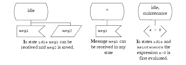
the message could be coming from an external channel, or it could be a timer message started by the process itself.
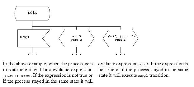
when reaching a state with continuous signals, the expressions in the continuous signals are evaluated following the defined priorities. All continuous signal expressions are evaluated before the message input !
the incoming message can not be treated in the current process state. It is saved until the process state changes. When the process state has changed the saved messages are treated first (before any other messages in the queue but after continuous signals).
Some transitions can be valid for several states, the different state names are then listed separated by a comma. A star ('*') means all states.
Examples:
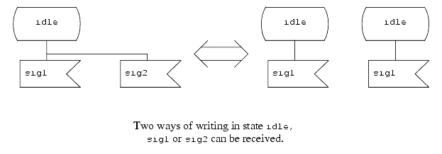
A process in a specific state can receive several types of messages or treat several continuous signals. To represent such a situation it is possible to have several message inputs connected to the state or to split the state in several symbols with the same name.
Examples:
4.3 - Stop
A process can terminate itself with the stop symbol.
Note a process can not kill another process, it can only kill itself.
There is no syntax for that symbol.
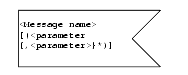
4.4 - Message input
The message input symbol represent the type of message that is expected in an SDL-RT state. It always follows an SDL-RT state symbol and if received the symbols following the input are executed.
An input has a name and can come with parameters. To receive the parameters it is necessary to declare the variables that will be assigned to the parameters values in accordance with the message definition.
The syntax in the message input symbol is the following:
<Message name> [(<parameter name> {, <parameter name>}*)]
<parameter name> is a variable that needs to be declared.
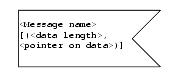
If the parameter type is undeclared it is still possible to transmit unstructured data with the parameter length and a pointer on the data.
If the parameter length is unknown, because the parameters are unstructured data, it is also possible to get the parameter length assigned to a pre-declared variable.
The syntax in the message input symbol is the following:
<Message name> [(<data length>, <pointer on data>)]
<data length> is a variable that needs to be declared as a long.
<pointer on data> is a variable that needs to be declared as an unsigned char *.
Examples:
4.5 - Message output
A message output is used to exchange information. It puts data in the receiver's message queue in an asynchronous way.
When a message has parameters, user defined local variables are used to assign the parameters. General syntax in the output symbol is:
<message name>[(<parameter value> {,<parameter value>}*)] TO_XXX...
If the parameter is undefined the length of data and a pointer on the data can be provided. In that case, the symbol syntax is:
<message name>[(<data length>, <pointer on data>)] TO_XXX...
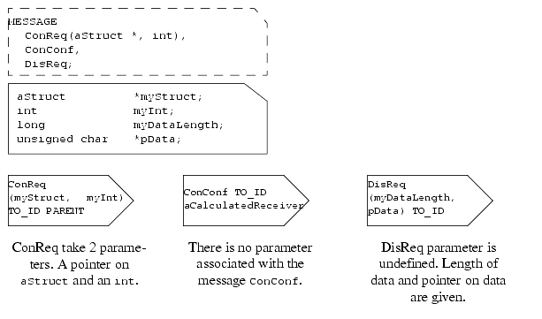
The syntax in the message output symbol can be written in several ways depending if the queue Id or the name of the receiver is known or not. A message can be sent to a queue Id or to a process name or via a channel or a gate. When communicating with the environment, a special syntax is provided.
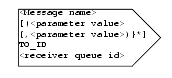
4.5.1 To a queue Id
The symbol syntax is:
<message name>[(<parameter value> {,<parameter value>}*)] TO_ID <receiver queue id>
It can take the value given by the SDL-RT keywords:
PARENT The queue id of the parent process.
SELF The queue id of the current process.
OFFSPRING The queue id of the last created process if any or NULL if none.
SENDER The queue id of the sender of the last received message.
Examples:
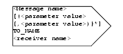
4.5.2 To a process name
The syntax is:
<message name>[(<parameter value> {,<parameter value>}*)] TO_NAME <receiver name>
<receiver name> is the name of a process if unique or it can be ENV when simulating and the message is sent out of the SDL system.
Examples:
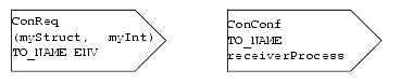
Note:
If several instances have the same process name (several instances of the same process for example), the 'TO_NAME' will send the message to the first created process with the corresponding name. Therefore this method should no be used when the process name is not unique within the system.
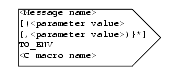
4.5.3 To the environment
The symbol syntax is:
<message name>[(<parameter value> {,<parameter value>}*)] TO_ENV [<C macro name>]
<C macro name> is the name of the macro that will be called when this SDL output symbol is hit. The macro will take 3 parameters:
The fields of the implicit C struct will have the same type as the types defined for the message.
- name of message,
- length of a C struct that contains all parameters,
- pointer on the C struct containing all parameters.
If no macro is declared the message will be sent to the environment.
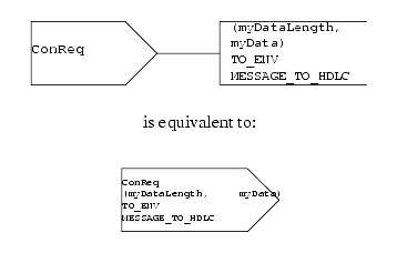
Example:
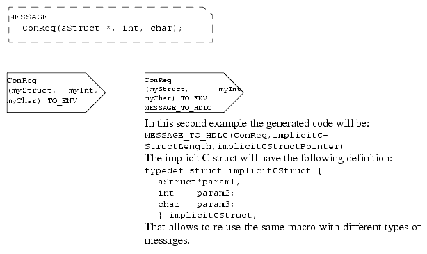
Note:
The implicit C struct memory space is implictly allocated and it is the C macro responsability to ensure it will be freed at some point.
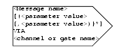
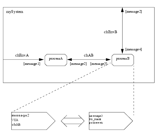
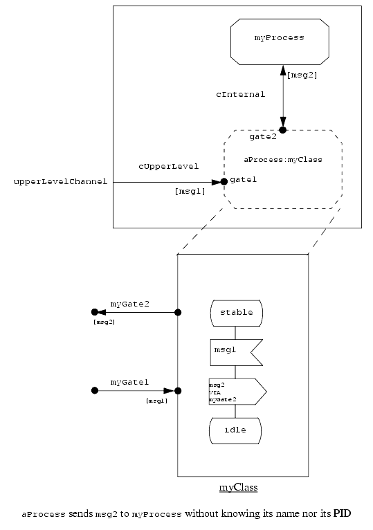
4.5.4 Via a channel or a gate
A message can be sent via a channel in the case of a process or via a gate in the case of a process class.
The symbol syntax is:
<message name>[(<parameter value> {,<parameter value>}*)] VIA <channel or gate name>
<channel or gate name> is the name of the channel or gate the message will go through.
This concept is especially usefull when using object orientation since classes are not supposed to know their environment; so messages are sent via the gates that will be connected to the surrouding environment when instanciated.
Examples:
With the architecture defined above, both outputs are equivalent.
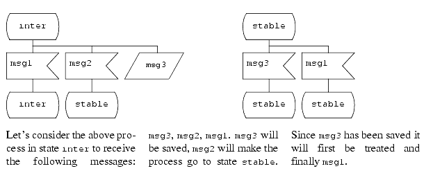
4.6 - Message save
A process may have intermediate states that can not deal with new request until the on-going job is done. These new requests should not be lost but kept until the process reaches a stable state. Save concept has been made for that matter, it basically holds the message until it can be treated.
The Save symbol is followed by no symbol. When the process changes to a new state the saved messages will be the first to be treated (after continuous signals if any).
The symbol syntax is:
<message name>
Even if the message has parameters.
Example:
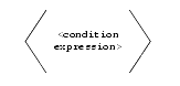
4.7 - Continuous signal
A continuous signal is an expression that is evaluated right after a process reaches a new state. It is evaluated before any message input or saved messages.
The continuous signal expression to evaluate can contain any standard C expression that returns a C true/false expression. Since an SDL state can contain several continuous signal a priority level needs to be defined with the PRIO keyword. Lower values correspond to higher priorities. A continuous signal symbol can be followed by any other symbol except another continuous signal or a message input. The syntax is:
<C condition expression>
PRIO <priority level>
Example:
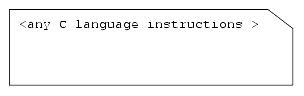
4.8 - Action
An action symbol contains a set of instructions in C code. The syntax is the one of C language.
Example:
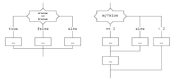
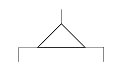
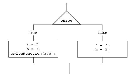
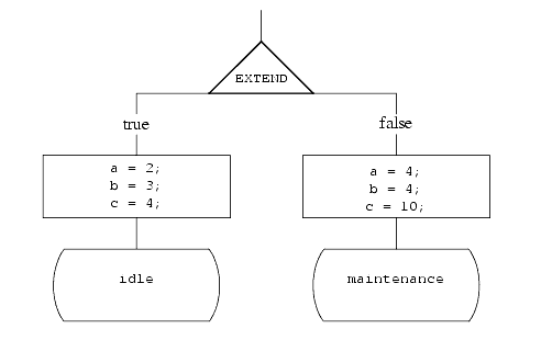
4.9 - Decision
A decision symbol can be seen as a C switch / case.
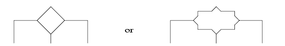
Since it is graphical and therefore uses quite some space on the diagram it is recommended to use it when its result modifies the resulting process state. The decision symbol is a diamond with branches. Since a diamond is one of the worst shape to put text in it, it can be a "diamonded" rectangle. Each branch can be seen as a case of the switch.
The expression to evaluate in the symbol can contain:
The values of the branches have keyword expressions such as:
- any standard C expression that returns a C true/false expression,
- an expression that will be evaluated against the values in the decision branches.
The else branch contains the default branch if no other branch made it.
Examples:
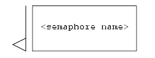
4.10 - Semaphore take
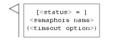
The Semaphore take symbol is used when the process attempts to take a semaphore.
To take a semaphore, the syntax in the 'semaphore take SDL-RT graphical symbol' is:
[<status> = ] <semaphore name>(<timeout option>)
where <timeout option> is:
Hangs on the semaphore forever if not available.
Does not hang on the semaphore at all if not available.
Hangs on the semaphore the specified number of ticks if not available.
and <status> is:
If the semaphore has been successfully taken
If the semaphore was not found or if the take attempt timed out.
4.11 - Semaphore give
To give a semaphore, the syntax in the 'semaphore give SDL-RT graphical symbol' is:
<semaphore name>
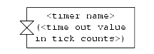
4.12 - Timer start
To start a timer the syntax in the 'start timer SDL-RT graphical symbol' is :
<timer name>(<time value in tick counts>)
<time value in tick counts> is usually an 'int' but is RTOS and target dependant.
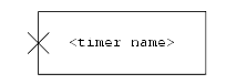
4.13 - Timer stop
To cancel a timer the syntax in the 'cancel timer SDL-RT graphical symbol' is :
<timer name>
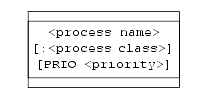
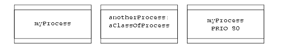
4.14 - Task creation
To create a process the syntax in the create process symbol is:
<process name>[:<process class>] [PRIO <priority>]
to create one instance of <process class> named <process name> with priority <priority>.
Examples:
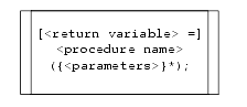
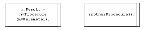
4.15 - Procedure call
The procedure call symbol is used to call an SDL-RT procedure (Cf. "Procedure declaration" on page 38). Since it is possible to call any C function in an SDL-RT action symbol it is important to note SDL-RT procedures are different because they know the calling process context, e.g. SDL-RT keywords such as SENDER, OFFSPRING, PARENT are the ones of the calling process.
The syntax in the procedure call SDL graphical symbol is the standard C syntax:
[<return variable> =] <procedure name>({<parameters>}*);
Examples:
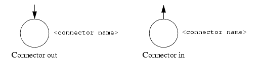
4.16 - Connectors
Connectors are used to:
A connector-out symbol has a name that relates to a connector-in. The flow of execution goes from the connector out to the connector in symbol.
- split a transition into several pieces so that the diagram stays legible and printable,
- to gather different branches to a same point.
A connector contains a name that has to be unique in the process. The syntax is:
<connector name>
Examples:
4.17 - Transition option
Transition options are similar to C #ifdef.
The branches of the symbol have values true or false. The true branch is defined when the expression is defined so the equivalent C code is:
#ifdef <expression>
The branches can stay separated to the end of the transition or they can meet again and close the option as would do an #endif.
Examples:
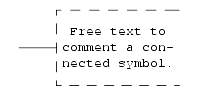
4.18 - Comment
The comment symbol allows to write any type of informal text and connect it to the desired symbol. If needed the comment symbol can be left unconnected.
Example:
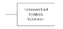
4.19 - Extension
The extension symbol is used to complete an expression in a symbol. The expression in the extension symbol is considered part of the expression in the connected symbol. Therefore the syntax is the one of the connected symbol.
Example:
4.20 - Procedure start
This symbol is specific to a procedure diagram. It indicates the procedure entry point.
There is no syntax associated with this symbol.
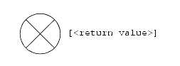
4.21 - Procedure return
This symbol is specific to a procedure diagram. It indicates the end of the procedure.
This symbol is specific to a procedure diagram. It indicates the end of the procedure. If the procedure has a return value it should be placed by the symbol.
4.22 - Text symbol
This symbol is used to declare C types variables.
The syntax is C language syntax.
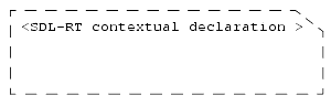
4.23 - Additional heading symbol
This symbol is used to declare SDL-RT specific headings.
It has a specific syntax depending in which diagram it is used.
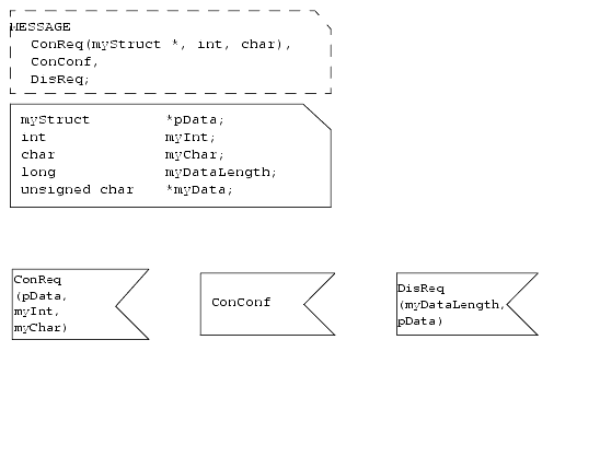
Allows to declare messages and messages lists:
MESSAGE <message name> [(<param type>)] {,<msg name> [(<param type>)]};
MESSAGE_LIST <message list name> = <message name> {,<message name>}*;
Allows to specify the superclass to inherit from:
INHERITS <superclass name>;
Allows to specify the package to use:
USE <package name>;
Allows to define the stack size:
STACK <stack size value>;
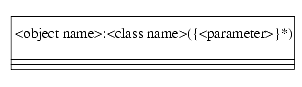
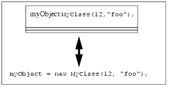
4.24 - Object creation symbol
This is equivalent to creating an instance of class <class name> named <object name>.
This symbol can be used by tools to check consistency between the dynamic SDL view and the static UML view.
Examples:
4.25 - Super class transition symbol
This symbol is used to call the corresponding super class transition. It can be used anywhere in the transition between the "Message input" symbol and the next "State" symbol. The sub class transition signature must be exactly the same as the super class transition signature including the variale names. More explanations in "Object orientation" on page 65.
4.26 - Super class next state symbol
This symbol is used to set the next state to the one of the super class. It replaces the standard "State" symbol at the end of a transition. More explanations in "Object orientation" on page 65.
4.27 - Composite state
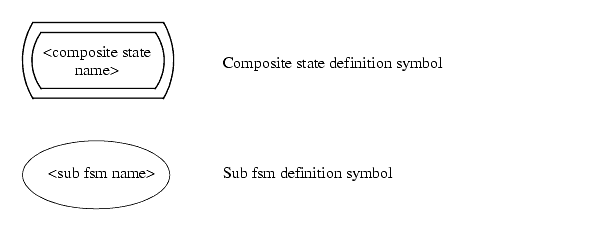
4.27.1 Composite state definition
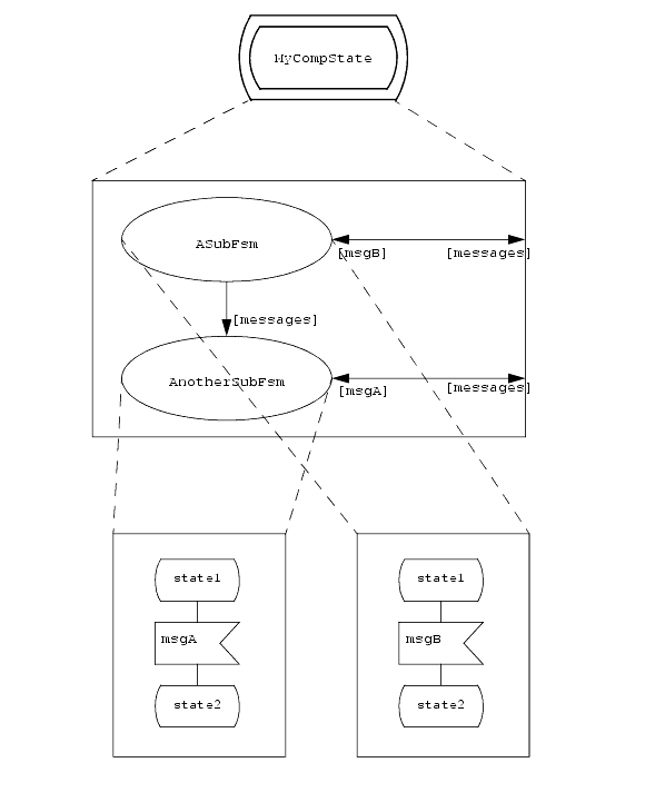
A composite state is a state composed of sub finite state machines. Each sub-fsm handles a different subset of messages. The super-fsm also handles its own inputs. When a message is for one of the sub-fsm the super-state does not change. But when a message is for the super-fsm all sub-fsm are terminated.
The Sub-fsm definition symbols are connected to channels. Each message is routed to a specific sub-fsm, the same message can not be received by two different sub-fsm.
The definition is done as described below:
This mecanism is currently known as "state hierarchy" in UML or "services" in SDL.
4.27.2 Composite state usage
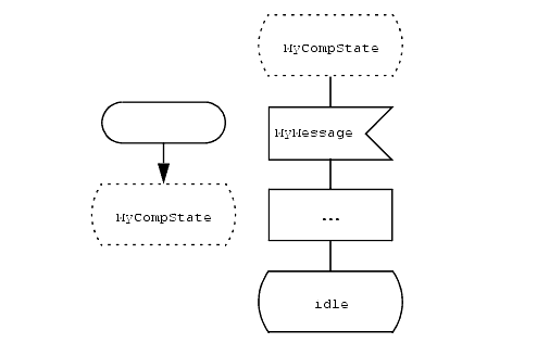
A dashed state symbol is used to indicate the fsm is getting into a composite state.
When in the composite state MyCompState, messages are routed toward the corresponding sub-fsm. When receiving the MyMessage message, the sub-fsm are terminated and the super fsm transition is executed. If the same message can be received by the super fsm and by one of the sub fsm, the super fsm transition has priority.
4.28 - Symbols ordering
The following table shows which symbols can be connected to a specific symbol.
The symbol in this column can be followed by the ticked symbols in its row.
The table above should be read row by row. The symbol in the left column can be followed by the ticked symbols on its row. For example the stop symbol can not be followed by any other symbol. The state symbol can be followed by input, save, or continuous signal symbols.
 http://www.sdl-rt.org info@sdl-rt.org |